Wednesday, 21 November 2012

Job Sheet

Job Sheet

Job sheets are an legal document, if there is a disput over the job at a later date thenyou can pull the job sheet to tell what was done at what time & who preformed the task.
With out it you could loose the case!

JOB SHEET

1.Job# :So you know how many customers had come.

2.Date: This needs to be recorded when the job is done.

3.Customers name:so you know who you are doing the job for.

4.Address:If they drop the car off so you know where to send it back to them.

5.Phones:So we can contact the the customer when needed

6.Chassis/engine: To confirm and identify which vehicle.

7.Registration:To confirm and identify which vehicle.

8.Odometer:To confirm mileage work done at.

9.NZ new or import: To confirm which model

10.Contact name:To know who you are talking to when the work is done for the vehicle to be collected.

11.Customer signature:To give authority for work to be completed.

12.Work requested:So you know what work needs to be done.

13Labour:To confirm how long the job took.

14.Parts fitted:What was fitted to the vehicle and how much it cost.

15.Invoice total:How much the customer is expected to pay for work done.

16.WOF due date:To remind the customer to get it renewed on time.

Tuesday, 23 October 2012

Spring Types

Spring Types

Copied From Google Images
There are four different kinds of springs:

Coil Springs

Leaf Springs

Torsion Bars

Rubber Springs

Coil Springs:

Coil springs can look alike but give very different load ratings, Which are often colour coded for identification.


Leaf Springs:

Driving thrust transfers through the front half of the spring to the fixed shackle point


Torsion bars:

are fixed to the chassis or the sub - frame at one end & the suspension control arm at the other end.
Load on the suspension causes the bar to twist around the center & to provide the springing action.

Rubber Springs:


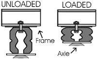
Increasing the load on the suspension causes the rubber cone to act like a spring being deformed.
Once the load has been removed the rubber spring retracts to it's proper shape.

Suspension Principles

Suspension Principles

Principles Of Suspension:

Sprung mass - is the vehicles parts that rest on the springs, such as the body, frame & the engine.

Unsprung mass - Is the parts of the vehicle that sit or connect around the vicinity of the suspension. Meaning they are the parts that are not supported by the springs, Such as the steering, suspension, wheels & brake assemblies.

Suspension Force:

Picture Copied From Google Images
Leaf Springs


Leaf spring applied force by flattening out under load.


Coil springs are designed to absorb the force of impact by twisting.
And torsion bars are designed twist around there center.


Unsprung Weight:

Is parts of the vehicle that are not supported by the vehicle suspension.

Dampening:

Copied From Google Images

Is the part that prevents or reduces the bouncing effect of oscillation.
This is where shock absorbers are used most often.

Body Chassis Type

Body Chassis Type

Picture Copied From Google Images

About:

The chassis is the under body of the vehicle, to which the upper body is mounted on along with the wheels & the rest of the vehicle.

Ladder Chassis:

The top picture is known as the ladder chassis, these were designed in the early 60's & used on nearly all automotive vehicles.

Advantages - Just that these are cheap & are easy to produce.

Disadvantages - Because the middle part of the this structure is very low compared to other designs & makes it very hard to deal with the heavy loads or bumps.

Backbone Chassis:

Picture Copied From Google Images
The backbone consist's of long tubular centre piece to join the front rear suspension together. The picture above is of a double backbone chassis, instead of a round centre piece it has two solid rectangular pieces join the front & back!

Advantages - Strong enough for small sport cars & is easy to produce & cheap.

Disadvantages - This design is unfortunately not safe in a crash, The back bone does not provide protection against side impact crash

Tubular Space Frame:

Picture Copied From Google Images
Tubular space frame consist of many circular sections of tubes & can also consist of of square shaped ones. The square shaped tubes are made to join sections together easier & the circular tubes are designed for maximum strength. Having so many cross section gives the space frame strength all round.

Advantages - Very strong in every direction.

Disadvantages - Its very complex & costly time consuming to be built.

Tuesday, 2 October 2012

Brake Calliper

Brake Calliper

The brake calliper:

The brake callipers would have to be one of the vehicles most important components out of all the brake components.
These are fitted over the brake rotor like a clamp & push against the pads to slow the vehicle down.
There are two types of callipers - Floating & fixed.

Floating Callipers:

These are when the pads secured to the body of the calliper between the piston & the rotor, The side between the body & the rotor.

Fixed Callipers:

These have two or more pistons on either side of the housing & are crossed drilled to allow the fluid to flow to all pistons evenly.

Off car vehicle testing:
Dissembling the calliper & testing all components.
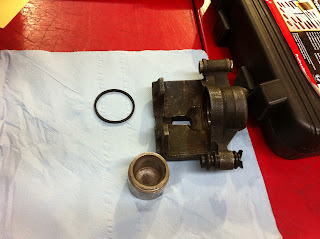
(Left & below) is of the piston which pushes against the pad, the fluid pressure builds from behind.

We are looking for anything that could possibly cause the fluid to leak out from behind out on to the pads or loosing pressure.

Deep scratches
Broken/ chips from the end


Using the vernier calliper we then measure the  inside of the calliper to make sure that inside hasn't been worn from the piston moving back & forth. 

The same is done with the piston as it was with the calliper. We need to check specs to make sure it pass's.


Once all seals, calliper, piston are all checked & everything is fine.
Our one was not & needed a new piston & a couple of seal

Monday, 1 October 2012

Drum Brakes

Drum Brakes

The pic above is of a drum brake that has been stripped of everything inside.
There are 3 types of brake drums!
The drum brakes consist of the following components:

2 x Shoe's - 1 x Rear Shoe, 1 x Front shoe
1 x Parking Brake
1 x Parking Brake Cable & Spring
1 x Wheel Cylinder
2 x Brake Shoe Tension Springs
2 x brake Shoe retaining Clips

The above is a Servo Drum Brake System
There is also Symplex & Duplex


The video on the left is of Hans our tutor showing us how the brake drum cover comes off. These tend to stick a bit & may need a bit of a tap to loosen it.

To the right we have the drum brake is fully dismantled, Both shoes, clips & all springs have been pulled off. After everything is off then we can start measuring all components. 

(Left) Here the brake line has been clamp 

(Right) loosing the wheel cylinder so we are able to do of car testing on it!


(Left) Once I had pulled the drum apart, me & my partner had checked everything that needed checking then my partner put the drum back together.

Tuesday, 11 September 2012

Steering Rack

Steering Rack

The steering rack is what helps turn the wheels of the vehicle. It comprises of many components but two of the most important pieces is the rack & pinion.
The pinion is a gear that engages on the gear called the rack, The pinion would be the most interesting part out of the steering rack.
This has several small holes in it & rotates to open up each hole to let oil through to lubricate each movement.

(Right) we have the right hand side boot & tie rod end.

(left) Is the left hand side tie rod end and boot.
The boot helps keep the lubricant from leaking out.
The tie rod connects to a spindle or steering arm.

(Left) is of the, inner ball joint, tire rod end & the housing.
The housing is what holds the pinion & allows the oil to flow through to the right parts.

(Right) is of the right hand side ball joint & the tire rod.
The ball joint allows the tire rod to move as the suspension moves up & down.

(Left) is of the housing & all so the oil lines the feed the oil down to the rack.
Also the pic below is showing the oil lines running down along the housing.

(left) is the housing which has been dissembled.
The pinion gear has been removed & the oil line.
When I say oil lines I mean power steering oil.

The power steering lines been removed & also the left hand side boot.
The pinion gear is to the left,
The pinion gear allows the rack to turn, when this action is applied the top half of this part will turn to open & close off the tiny holes to allow the lubricant through.


To remove the rack from the body, the lock washer & the rack bush both need to be removed.
In our case we had to drill a small hole through the body just above the lock washer to pop it out, after that the rack bush just slid out then rack arm needed to be slightly taped out.

(Right) is of us checking the ovality of the rack, This is to find out if the rack has been bent or not. 

Once all parts have been checked & replaced if needed to be replaced then we could put it back together, Our steering rack was in good condition!

Wednesday, 5 September 2012

Wheel Alignment

Wheel Alignment

Wheel alignments consists of adjusting the angles of the wheels so that they are straight up & down to the ground and parallel to each other. The wheel alignment is so the vehicle drives straight & also to maximum the life of the tyre.
Pre checks are done before the alignment is to take place some of these are:

Tyre Pressure

Tyre Condition

Any Play on the ball joints, steering rack & rack end.

Check the spare tyre too

When checking the the tyre condition we needed to check for the wear of the tyre - Toe wear, camber wear, centre wear, edge wear, patch wear & also cup wear.

When doing the alignment the vehicle needs to be on a hoist as the hoist is more level than the ground.

To the left the vehicle has been pushed on to a set of turn tables.
These are so we are able turn the wheels freely.


The video on the left is of the plugs getting put on the wheel clamp. These are put on so we can securely attach the wheel clamp to the rim of the wheel.

These are showing how we attached the wheel clamp to the wheel of the vehicle.
The three plugs attach to the rim, The two arms of the clamp are what clamps to the face of the tyre.

It is critical that the clamp is put on how you see in the pics.
This is so when the camera is put on it will sit perfectly straight with the wheel.

The beam is what slide's into the wheel clamp, The bit that attaches to the clamp has a camera that lines up to the centre of the wheel & send the the info back to the computer.
There are four of these & each one has to be set on the right wheel of the vehicle.
Passenger side of the car is number one, driver two, left rear three & right rear four.

Each of these have a level on them so we can get it dead straight. The reason for this set up is so we can turn the wheel & the beam will stay straight with out turning with the wheel

This showing what we see when we are doing the alignment. When turning the wheels on the vehicle, the wheels on the computer will light up green as we turn them 90 degrees each time.

This checking the run out of the wheels.

The video on the right is showing how the wheel run out is done.

Thursday, 30 August 2012

Replacing Brakes

Measuring Rotors & Brakes


Simply remove the bottom sliding pin on the calliper, The calliper will then move up just like the pic above. Once the  calliper is out of the way then the brake pads should slide out, sometimes they might need a tap.

The calliper - Is what the brake line runs to, to the front brakes & pumps the fluid behind the the piston.
The piston is what pushes against the inside pad.
The calliper moves on sliding pins &  pulls against the outside pad.

The sliding pin helps the calliper move, It will most all ways be the bottom sliding pin that is removed to get the pads off.

Once the sliding pin has been removed then the calliper will slide up.
Remember if the pads need replacing the piston will need to pushed back. A G-clamp can do this with a piece of small timber.
When the calliper might need a bit of a nudge to get out.

Once everything has been removed & we can see the rotors, then we can start our visual inspection.


The pads removed!
With the shims.

The three pics below are showing how to measure the thickness of the pads using an Vernier Calliper


When checking the pads we need to check for even wear, Check the shims for cracks or even rust.


These rotors are vented rotors which means the holes/vents on the side are there to help cool down the rotors when there is braking applied & begin to get hot.

When measuring the rotors we are using a Micro Meter to check the thickness of the rotor.
We are also looking for Cracks, rust & deep scratches. If the rotor is within specs then we can make a decision if it needs to be machined or replaced.


The pic on the left  is showing the back right drum & disk. Not every vehicle will have these, Some will just have a drum. When servicing the back brakes we needed to remove the calliper completely.
How this one works is when the piston winds on to the back brake pad. 

The pic on the right is showing the back drum & disk
Another thing to measure is the run out of the rotor, by doing this we use the DTI Gauge. Unfortunately I didn't get any photos of this.