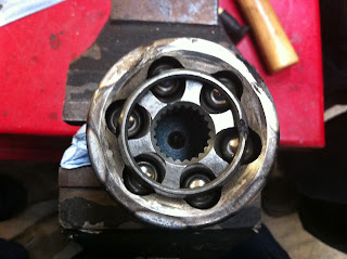
Driveshaft and cross type universal joints
Checking the Driveshaft Run Out:
Before dismantling the driveshaft, the driveshaft needs to be set up on a couple of vee bocks. Close to each universal joints. A dial test indicator is used to check the that the driveshaft is still correctly balanced. This done by checking ovality, also manufacture specifications are needed to complete this first task.
Dismantling & Checking the driveshaft:
Using soft face jaws on a vice, gently secure the driveshaft in the vice.
Once secure then we can check for play, roughness & binding.
To check for the above is a simple step - Move joint up & down & side to side.
To start dismantling the joint we first needed to pop off the snap rings or sometimes instead of snap there will be circlips.
To get these off is down with one or two flat head screw drivers.
The pic on the left is showing you this simple process.
The pic on the right is of the snap rings.
When knocking the caps out, the driveshaft needs to be rested on the vice while the opposite cap gets gently hit with a bronze punch.
What will happen is that the opposite cap to the one getting hit will get gently pushed out.
Once the cap has been pushed out enough to grab with a peer of pliers or even might be easy to pull out with your fingers.
To get the other side off, the exact same process is done.
The bearing that fits onto the universal joint is called a needle bearing.
Inside there is many compacted needles with a lot of grease to allow the uni joint to move around.
These needles are to come out cleaned & replaced with new ones.
Pic on the left is of the universal joint, We check this for wear.
This joint is what allows the driveshaft to bend with out breaking.
The snap ring is what holds the needle bearing in place so it doesn't fall out and cause the joint to fall apart.
These can break when removing & putting them back on.

Once we had done all inspections and replaced what needed to be replaced, We could then begin to put everything back together.
By using two sockets, one small & and one big socket.
Before following the pic on the right, The needle bearings need to be put through the holes & joined on to the universal joint. Make sure that there is enough grease applied to the areas needed. Once bearings have lined up & have fitted in properly using the two sockets & soft face vice. Then we were able to to put the snap rings back on.
Once secure then we can check for play, roughness & binding.
To check for the above is a simple step - Move joint up & down & side to side.
To start dismantling the joint we first needed to pop off the snap rings or sometimes instead of snap there will be circlips.
To get these off is down with one or two flat head screw drivers.
The pic on the left is showing you this simple process.
The pic on the right is of the snap rings.
When knocking the caps out, the driveshaft needs to be rested on the vice while the opposite cap gets gently hit with a bronze punch.
What will happen is that the opposite cap to the one getting hit will get gently pushed out.
Once the cap has been pushed out enough to grab with a peer of pliers or even might be easy to pull out with your fingers.
To get the other side off, the exact same process is done.
The bearing that fits onto the universal joint is called a needle bearing.
Inside there is many compacted needles with a lot of grease to allow the uni joint to move around.
These needles are to come out cleaned & replaced with new ones.
Pic on the left is of the universal joint, We check this for wear.
This joint is what allows the driveshaft to bend with out breaking.
The snap ring is what holds the needle bearing in place so it doesn't fall out and cause the joint to fall apart.
These can break when removing & putting them back on.

The pic on the right is showing you the counter weights that help balance out the driveshaft.
Once all parts have been cleaned & inspected & new parts replacing old if need be.Once we had done all inspections and replaced what needed to be replaced, We could then begin to put everything back together.
By using two sockets, one small & and one big socket.
Before following the pic on the right, The needle bearings need to be put through the holes & joined on to the universal joint. Make sure that there is enough grease applied to the areas needed. Once bearings have lined up & have fitted in properly using the two sockets & soft face vice. Then we were able to to put the snap rings back on.
When everything is back together the Joint should move about & should be a tad tight.


