Wednesday, 26 June 2013

F1 Engineering and Development - Replication or Simulation?

Many race teams spend massive amounts of their budget on test systems and instrumentation at all phases of the powertrain development process. In F1 this is particularly pertinent due to the limited amount of track time available for testing. However, this investment does not always guarantee success, many large teams, with the most sophisticated facilities have struggled, and many teams have done very well, with limited facilities. At the end of the day, it is all about the team!

However, one thing that comes up many times is the question – How to get closer to reality? But is it really necessary, especially when balanced against the cost of achieving it! Many teams have or are moving to transient or dynamic powertrain test systems. With the associated control systems, these have the advantage of being able operate and load the powertrain, during testing, in a way that is much closer to real operating conditions when compared to a steady state test. This is particularly useful for establishing the engine response and performance during transients (where, in most cases, the engine spends most of its life). In addition, durability tests are much more accurate for predicating and validating engine and component life.

F1 PURE Toyota Motorsport
Fig 1 - An F1 Engine test facility (Toyota Motorsport, Cologne)

In many test system, there are two main ways to try to replicate ‘real life’, assuming that you have a control system with a fast enough controller, and a 4-quadrant dynamometer with fast enough torque build up time, and a good inertia match to the unit under test. You can achieve very fast transient response, generally good enough to be able to follow a speed/throttle profile generated from telemetry or track simulation data. This is often known as replication – and is a useful test mode as it is relatively simple to get up and running, due to the fact that sophisticated simulation models are not generally needed. It is useful for validation of the engines load response, also for checking transient calibration/mapping and for endurance testing based on defined operation conditions. The compromise is that high dynamic components are not generally simulated. These components can have a significant effect on the powertrain during operation. In particular, component durability is more difficult to establish as the test systems does not have the same Eigen frequencies as a powertrain mounted in the vehicle, with the associated ancillary components.

F1 Renault engine V8
Fig 2 - Renault sport current engine (RS27) for F1

The next step closer to reality is to be able to ‘simulate’ as many of the high dynamic frequencies relating to the powertrain as possible. To do this, the dynamometer must have very low inertia in combination with a very fast, real-time controller in order to be able to simulate true ‘zero’ inertia when required, particularly important for simulation of gearshifts, and torque steps during ignition cuts.

In addition to this hardware, a sophisticated software simulation environment must exist to provide the demand values to the dynamometer controller, at a sufficiently high frequency to be able to generate the oscillation frequencies of the powertrain in each gear. In addition, this environment must allow characterisation and parameterisation of the vehicle dynamics, aerodynamics and driver response/behaviour. The more sophisticated the environment, the more parameters need characterising and setting. This can then take days to set the test system up for a test run. So, in practice, many teams tend to use the same test environment setting for every given test mode. There simply isn’t time to reprogram the test system with every engine change!

Heat Motor Generator Unit
Fig 3 - Renault sport HMGU (Heat Motor Generator Unit), for use in next years F1 power unit concept (engines are now power units according to Renault)

What direction for the future then – simulation environments are very effective at accelerating development processes, and are essential in todays world of the increasing complex variables to be optimised in any system – engine, transmission, powertrain, aerodynamics. But we’ll always need to test in order to validate any simulation and the closer the test environment to reality, the better the data, in order to validate simulations, and optimise the system!

Fig 4 - A typical test bed arrangement for High-performance engine testing - allows testing of engine only (with test system gearbox in place, as shown) or, powertrain (move test system gearbox out, use vehicle transmission)

Saturday, 22 June 2013

Technology focus - Diesel Common Rail - Pressure Wave compensation

A common rail diesel fuel system is an impressive bit of mass produced Engineering! The rail and injectors operate a extremely high pressures, in an under bonnet environment, and generally speaking, are quite durable and long lasting. The components in the fuel path are capable of metering accurately, fuel quantities from down to a few milligrams per stroke, up to the required amount for full load - approximately an order of magnitude difference. 

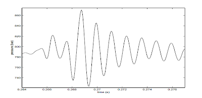
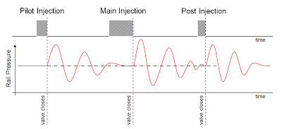
Clever stuff - but one thing to be considered in this system is the basic physics in fluid dynamics! In order to deliver the correct quantity of fuel, the injector opening time and pressure are used as basic parameters - i.e. increase the pressure and/or opening time and you'll get more fuel delivered into the cylinder! However, when the injector opens/closes, a pressure wave is generated which reflects back within the common rail, and then bounces back to the injector. This has the effect of altering the actual pressure at the injector momentarily. So, where multiple injection events occur - this can mean, at the precise moment the injector opens, the pressure could be higher or lower than required. Not good - this invalidates the calculation done by the ECU for the required fuel as it cannot be accurately delivered to the engine - this can affect badly affect emissions, fuel consumption and drivability at certain engine operating conditions.


Fig 1 - Pressure waves from one injection event can affect a subsequent event with respect to the amount of fuel delivered


The pressure wave effect is well established in engine technology - for example, it is used in variable length, tuned intake runners/manifolds, in order to provide a pressure wave supercharging effects. It is also the basic principle used in an expansion chamber, as seen on performance 2 stroke engines - in this case, the exhaust pressures waves are used to help scavenge the cylinder and assist the gas exchange process. The effect itself is very dependant on a number of environmental conditions, mainly, pressure, temperature and volume, also frequency and amplitude of the excitation event (hence the shape of an expansion chamber which has a tuned volume to coincide the effect at the optimum engine speed for maximum power).

Fig 2 - Actual pressure at the injector due to pressure wave effects

The solution to this common rail problem is to 'calibrate' it out. There is a function in the ECU which can provide a compensation for the effect. This function takes into account the main parameters which characterise the effect - namely injection quantities of each event, the separation distance between events and the actual rail pressure. There are calibration maps than need populating with data derived from a specific test process, this allows the effect to be measured.

Fig 3 - calibration maps for pressure wave compensation

The procedure involves running the engine in a very stable speed/load condition whilst measuring fuel consumption with high accuracy, whilst varying the separation time between injector events. After measurement and modelling, a simple 2D curve showing the effect very clearly, can be observed

Fig 4 - Effect of pressure waves on actual fuel consumed, as a function of injector separation time


This data can then be used in further analysis to populate the calibration maps in the correction function. That allows the ECU and Fuel injection system to always be able to provide the correct fuel quantity with respect to operating condition and environment. Note that during this procedure, a set of highly accurate, calibrated injectors is used (not a standard set which are produced to normal production tolerances, they would not be accurate enough).

Monday, 10 June 2013

Vehicle Battery Testing – for accurate diagnostics

Modern vehicles have sophisticated energy requirements, and very sophisticated electronic consumers that need a stable, clean voltage supply. Already workshops are seeing obscure faults with electronic systems, including fault code errors, brought on by failing batteries. 

Traditionally, a failing battery would manifest itself by having insufficient power to crank the engine over and start the vehicle. Often more apparent in the winter months, when cold starts need more torque to overcome the friction of a cold engine, with thicker, cold lubricating oil. However, with modern vehicles, a failing battery is likely to produce a fault, of an unrelated nature, before this ‘non start’ symptom occurs. Battery technology has also progressed in line with the vehicle systems, and a different method of establishing the serviceability is now available, and more appropriate. Let’s take a look at this new generation testing technology, and how you can use it to provide better customer service through more accurate diagnosis.

Traditional test methods
There are 2 traditional methods of checking a wet, lead-acid, vehicle battery. The first is State of charge (SOC) which can be determined via measuring the specific gravity (SG) of the electrolyte in each cell with a hydrometer (but there is also a less accurate option, to measure the battery terminal voltage). Assuming the battery is reasonably well charged (>75%), then the performance test, indicating state-of-health (SOH), can be executed via a discharge test. This test is performed using a high rate discharge tester, with the appropriate load according to the battery capacity, and it would indicate the battery capability to supply a large current (as would be required under starting conditions). From these measurements, an experienced technician could make a judgement on the battery fitness for purpose.

 
Fig 1 - A high-rate discharge tester can indicate battery state-of-health, but still relies on the skill and judgement on the technician, in addition, there are several health and safety related issues to this approach! Note the tester in the picture is a fixed load, and not really suitable for the battery shown

Why are these test methods no longer applicable?
There are several reasons that these methods cannot really be applied:

  • Many modern battery types (VRLA, AGM, Gel) have no access to the cell electrolyte, thus hydrometer readings are simply not possible, although the battery may have a built in hydrometer, this is of limited use, it’s just an indicator. 
  • In order to execute a high-rate discharge test, the battery has to be disconnected from the vehicle – this can present time consuming problems for the technician e.g. lost radio codes, ECU memory loss etc.
  • There are health and safety issues, wet batteries contain acid, and generate volatile gases. High rate loads tests can create sparks and heat. All potential nightmares in a safety conscious, workshop environment. 
  • The measurements still rely on the knowledge and experience of the technician to make a judgement on the battery SOH. This is subjective and could be the source of inaccurate diagnoses.
The alternative – digital battery testers - conductance testing
Along with the progress in battery and vehicle technology, technology developments have also provided alternative methods in battery testing. Mainly in the form of battery testers that use a completely different approach to evaluating the battery condition, providing an objective measurement of battery condition and capability, along with a more accurate SOH assessment. These testers are intelligent units, with built in, menu guided test procedures. However, the biggest impact is due to the measurement technique itself – a conductance measurement.


Fig 2 –  Intelligent, digital battery testers are much safer, and more appropriate for testing modern battery technology

How does this work
The conductance test is a completely different method of establishing the battery condition and performance, and is ideally suited for modern vehicle battery test applications. It can also though be applied to older, wet lead-acid batteries as well. So, how does it work? The conductance tester applies an AC voltage, of known frequency and amplitude across the battery terminals, and monitors the subsequent current that flows with respect to phase shift and ripple.  The AC voltage is superimposed on the battery's DC voltage and acts as brief charge and discharge pulses. This information is utilized to calculate the impedance (measure of opposition to alternating current) of the battery, and from this the conductance value can established (impedance and conductance have a reciprocal relationship).


Fig 3 – AC voltage across the DC battery allows a measurement of the batteries conducting capability to be made

A conductance measurement provides a measure of the plate surface area, and this determines how much chemical reaction or power the battery can generate. It has been proven by experiment that a conductance value has direct correlation with the batteries capability to provide a current, which is normally specified via a Cold Crank Amps rating (CCA), but it is also a good indicator of battery state of health (SOH). Taking into account temperature and other parameters like age, chemistry etc. this test can accurately form the basis of an objective condition evaluation, and can be used as a reliable predictor of battery end-of-life.


Fig 4 – Conductance and Battery Capacity (with respect to the ability to supply large current) have a direct relationship


In order to provide a better understanding of the concept of the information provided by a conductance test, take a look at the comparison with a fuel tank. A healthy battery, when fully charged, can be compared directly to a full tank (i.e. full capacity). When discharged, it’s the same as an empty or low fuel tank (i.e. low capacity). However, when the battery has aged and SOH has declined, the reduced active plate surface area causes an effective reduction in the current supplying capability.


Fig 5 – Battery SOC and SOH, for illustration, compared to a fuel tank


Comparing with the fuel tank, this would be comparable to damage to the fuel tank, which has reduced its volume (for example, a large dent in the tank). So, even if you fill the tank, and the gauge shows full, the actual capacity of the fuel tank is reduced.

Summary
The conductance tester is an accurate, repeatable method. The tester can be applied to a connected battery in the vehicle. The test method is much safer for the operator and the vehicle. The result from the test is much more objective and factual. The tester can be applied to many modern battery technologies, and this is particularly important as battery technology is currently changing and adapting to new demands and load profiles generated by the latest technologies to reduce vehicle tailpipe emissions, namely stop/start and energy recovery technologies. This is an addition to smart energy management and battery charging systems, already seen in service on many current vehicles.


Monday, 3 June 2013

Automotive Diagnostics - an overview

The diagnostic skill of a technician in the Automotive Industry is one of the key attributes which sets aside the top-performing, most valuable members of technical staff from the rest. Skilled diagnostic technicians are a valuable asset in the Industry and most people who can demonstrate this ability are high-achieving Master Technicians who have the most interesting and challenging careers. 

Diagnostics skills are a combination of applied knowledge and experience, logical thought process, in combination with an inquisitive nature. That is, the instinct of a technical mind to understand how something works. A logical approach to fault finding is essential to avoid wasting time and money. If a fault occurs on a vehicle which is a known problem or you have come across before. Then, using your experience, you can optimise your time spent rectifying this fault as you have some direction. The diagnostic skill becomes apparent when you are looking at a problem you haven’t seen before. In this situation, many Technicians resort to changing component parts blindly, this is not acceptable for modern vehicles as these parts can be very expensive. A starting point is to use some method or philosophy to approach the problem. A simple but logical, generic process (as shown below) puts a structure behind your actions.


Fig 1 - Successive Approximation - a logical fault-finding process!

Successive approximation method
This method allows you to successively, physically check parts of a wiring circuit, in a logical way such that with each check, you will definitely get closer to the fault. This reduces the amount of time spent tracing faults electrical faults in the vehicle wiring system. If the circuit layout is not known, or is complex, then a wiring diagram will help considerably. The principle involves finding the ‘middle’ of the offending circuit path. Form this point you can check which side of the circuit has failed with the appropriate test tool. Once you identified this, you have immediately reduced the size of the problem by half! Next, you identify the half way point of the bad part of the circuit (above), then, make another check at this point. This technique rapidly reduces the size of the problem with each step. Finally, you will reach a point where the problem is easy to identify as you can locate a very specific area (for example, a junction block) where the problem has to exist. This technique is very powerful and can be applied to any circuit.

Dealing with Open circuits
Open circuits are identified normally by a loss of power. This can be easily checked with a voltmeter or test-lamp via an open-circuit test. Generally the voltmeter has the advantage that it does not damage any sensitive components but it cannot identify a high resistance in an unloaded circuit. That is, the voltmeter tells you that a connection exists which can supply the voltage, not how good that connection is! An ohmmeter can also to used to check for open circuits but the circuit or component must be completely un-powered. Also, low resistances cannot be tested effectively with a ohmmeter.

Dealing with Short Circuits
Short circuits are where a direct path to ground exists, In an electrical circuit the current will always take the easiest path, if this happens the circuit is overloaded and (hopefully) a fuse (or other protection device )will operate and protect the circuit. Short circuit detectors are available that switch the fault current on and off in the circuit (they are fitted in place of the blown fuse). It is then  possible to identify the position of the fault using a compass or inductive ammeter. This means that it is possible to locate the fault without removing trim. The problem is that a high current still flows momentarily and thus, if the wire in the faulty circuit is a small size, it can still overheat. A better solution is to use a high-wattage bulb (>21w), this will not overload the circuit but the intensity of the lamp allows you to distinguish a dead short from the normal circuit current. This method is particularly useful for tracing intermittent faults. Examining the fuse can give information about the nature of the fault. If the fuse has ‘blown’ then a dead short exists. If it has overheated then an overload has occurred (a faulty component?). If it has just fractured then the fuse itself could have fatigued and failed with no specific circuit fault.

Dealing with Parasitic Loads
Parasitic loads are current drawn whilst the vehicle is standing inoperative. Most vehicles have a small, standing current draw due to electronic components (~50mA) but more than this will flatten the battery over an extended period of say, a few days. In order to isolate a load of this kind an ammeter must be connected in circuit with the battery. By removing the fuses one-by-one of all the components which draw a quiescent current (quiescent = being in a state of repose; at rest; still; not moving) can be identified and eliminated, as once the offending circuit component fuse is disconnected, the drop in current draw will be seen at the ammeter. It is then possible to follow this current draw via the wiring system by disconnecting at appropriate wiring junctions, in this way the circuit component can be isolated.

Voltage Drop Testing
Volt drop testing is a dynamic test of the circuit under operating conditions and is a very reliable way of determining the integrity of the circuit and its components. With this technique, problem resistances in circuits which carry a significant current ( >3amps) can be clearly identified. For these circuits, even a resistance of 1 ohm can cause a problem (remember that V =IR, therefore a resistance of 1 ohm in a circuit carrying 3 amps will drop 3 volts across the resistance, that is 25% of the available voltage for a 12 volt system). Because the test is done whilst the circuit is operating, factors such as current flow and heating effect will be apparent. To test for volt drop, the voltmeter is placed in parallel  with the circuit section to be tested. During operation of the circuit, any unwanted resistance will show as a voltage reading. In general, not more than 10% of the system voltage should be dropped between the source (the battery) and the consumer (the load). Voltage drop measurements should be carried out on return (earth) as well as the supply side of the circuit and generally voltage dropped on the earth side should be lower.

On board diagnostics
Remember that many chassis and body system components now use the same communication methods and techniques to share information as Powertrain systems (e.g. CAN, LIN) and operate on the same network. Body and Chassis Diagnostic Trouble Codes (DTC’s) are defined in the OBD protocol standard and hence there is much useful information to be gained when troubleshooting by exploiting the OBD functionality. Generally, Powertrain codes start with a P, Body and Chassis codes start with a B and C respectively. For more sophisticated control systems, accessing the DTC’s should be the first step in a diagnostic procedure. In many systems, this will be the only way to start fault finding as the system and it’s components are so complex.

An example of some generic chassis codes is shown below:

C0000 - Vehicle Speed Information Circuit Malfunction
C0035 - Left Front Wheel Speed Circuit Malfunction
C0040 - Right Front Wheel Speed Circuit Malfunction
C0041 - Right Front Wheel Speed Sensor Circuit Range/Performance (EBCM)
C0045 - Left Rear Wheel Speed Circuit Malfunction
C0046 - Left Rear Wheel Speed Sensor Circuit Range/Performance (EBCM)
C0050 - Right Rear Wheel Speed Circuit Malfunction
C0051 - LF Wheel Speed Sensor Circuit Range/Performance (EBCM)
C0060 - Left Front ABS Solenoid #1 Circuit Malfunction
C0065 - Left Front ABS Solenoid #2 Circuit Malfunction
C0070 - Right Front ABS Solenoid #1 Circuit Malfunction
C0075 - Right Front ABS Solenoid #2 Circuit Malfunction
C0080 - Left Rear ABS Solenoid #1 Circuit Malfunction
C0085 - Left Rear ABS Solenoid #2 Circuit Malfunction
C0090 - Right Rear ABS Solenoid #1 Circuit Malfunction
C0095 - Right Rear ABS Solenoid #2 Circuit Malfunction
C0110 - Pump Motor Circuit Malfunction
C0121 - Valve Relay Circuit Malfunction
C0128 - Low Brake Fluid Circuit Low
C0141 - Left TCS Solenoid #1 Circuit Malfunction
C0146 - Left TCS Solenoid #2 Circuit Malfunction
C0151 - Right TCS Solenoid #1 Circuit Malfunction
C0156 - Right TCS Solenoid #2 Circuit Malfunction
C0161 - ABS/TCS Brake Switch Circuit Malfunction
C0221 - Right Front Wheel Speed Sensor Circuit Open
C0222 - Right Front Wheel Speed Signal Missing
C0223 - Right Front Wheel Speed Signal Erratic
C0225 - Left Front Wheel Speed Sensor Circuit Open
C0226 - Left Front Wheel Speed Signal Missing
C0227 - Left Front Wheel Speed Signal Erratic

An example of some generic Body codes is shown below:

B1200 Climate Control Pushbutton Circuit Failure 
B1201 Fuel Sender Circuit Failure 
B1202 Fuel Sender Circuit Open 
B1203 Fuel Sender Circuit Short To Battery 
B1204 Fuel Sender Circuit Short To Ground 
B1213 Anti-Theft Number of Programmed Keys Is Below Minimum 
B1216 Emergency & Road Side Assistance Switch Circuit Short to Ground 
B1217 Horn Relay Coil Circuit Failure 
B1218 Horn Relay Coil Circuit Short to Vbatt 
B1219 Fuel Tank Pressure Sensor Circuit Failure 
B1220 Fuel Tank Pressure Sensor Circuit Open 
B1222 Fuel Temperature Sensor #1 Circuit Failure 
B1223 Fuel Temperature Sensor #1 Circuit Open 
B1224 Fuel Temperature Sensor #1 Circuit Short to Battery 
B1225 Fuel Temperature Sensor #1 Circuit Short to Ground 
B1226 Fuel Temperature Sensor #2 Circuit Failure 
B1227 Fuel Temperature Sensor #2 Circuit Open 
B1228 Fuel Temperature Sensor #2 Circuit Short to Battery 
B1229 Fuel Temperature Sensor #2 Circuit Short to Ground 
B1231 Longitudinal Acceleration Threshold Exceeded


Key points and summary:
Try to employ a logical approach to your fault finding, this prevents wasting time and replacement of unnecessary components.
  • Try to familiarise yourself with the system and attempt to understand how the system works (assuming the information is available) this allows you to use your time more efficiently and effectively.
  • Use a heuristic approach, use your experience with similar problems or scenarios to optimise the use of your time dealing with the current problem in hand.
  • Always take the path of least resistance, test or check the components that are easiest to access first to prevent wasted time removing trim unnecessarily.
  • Never overlook the obvious, never assume anything, always check things out for yourself. Assume everybody else is an idiot and make your own checks to ensure that you always have the correct information during your investigation process.
  • Always gather as much information as you can. If available, use manuals and wiring diagrams, check them even if you think you know how the system works! If DTC’s are available and accessible, use them to help point you in the right direction to start dealing with the problem
  • When dealing with intermittent problems take a strategic approach, even though the systems can be complex there is no magic. If something doesn't work there is a reason, also problems don’t fix themselves, try to get to the root of the problem, if you don’t it will come back!