A common rail diesel fuel system is an impressive bit of mass produced Engineering! The rail and injectors operate a extremely high pressures, in an under bonnet environment, and generally speaking, are quite durable and long lasting. The components in the fuel path are capable of metering accurately, fuel quantities from down to a few milligrams per stroke, up to the required amount for full load - approximately an order of magnitude difference.
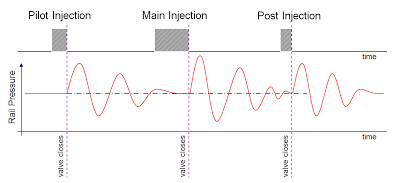
Clever stuff - but one thing to be considered in this system is the basic physics in fluid dynamics! In order to deliver the correct quantity of fuel, the injector opening time and pressure are used as basic parameters - i.e. increase the pressure and/or opening time and you'll get more fuel delivered into the cylinder! However, when the injector opens/closes, a pressure wave is generated which reflects back within the common rail, and then bounces back to the injector. This has the effect of altering the actual pressure at the injector momentarily. So, where multiple injection events occur - this can mean, at the precise moment the injector opens, the pressure could be higher or lower than required. Not good - this invalidates the calculation done by the ECU for the required fuel as it cannot be accurately delivered to the engine - this can affect badly affect emissions, fuel consumption and drivability at certain engine operating conditions.
Clever stuff - but one thing to be considered in this system is the basic physics in fluid dynamics! In order to deliver the correct quantity of fuel, the injector opening time and pressure are used as basic parameters - i.e. increase the pressure and/or opening time and you'll get more fuel delivered into the cylinder! However, when the injector opens/closes, a pressure wave is generated which reflects back within the common rail, and then bounces back to the injector. This has the effect of altering the actual pressure at the injector momentarily. So, where multiple injection events occur - this can mean, at the precise moment the injector opens, the pressure could be higher or lower than required. Not good - this invalidates the calculation done by the ECU for the required fuel as it cannot be accurately delivered to the engine - this can affect badly affect emissions, fuel consumption and drivability at certain engine operating conditions.
Fig 1 - Pressure waves from one injection event can affect a subsequent event with respect to the amount of fuel delivered
The pressure wave effect is well established in engine technology - for example, it is used in variable length, tuned intake runners/manifolds, in order to provide a pressure wave supercharging effects. It is also the basic principle used in an expansion chamber, as seen on performance 2 stroke engines - in this case, the exhaust pressures waves are used to help scavenge the cylinder and assist the gas exchange process. The effect itself is very dependant on a number of environmental conditions, mainly, pressure, temperature and volume, also frequency and amplitude of the excitation event (hence the shape of an expansion chamber which has a tuned volume to coincide the effect at the optimum engine speed for maximum power).
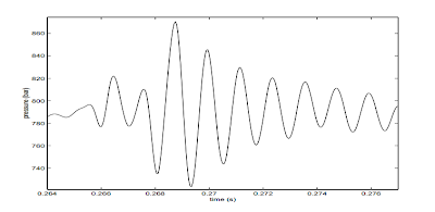
Fig 2 - Actual pressure at the injector due to pressure wave effects
The solution to this common rail problem is to 'calibrate' it out. There is a function in the ECU which can provide a compensation for the effect. This function takes into account the main parameters which characterise the effect - namely injection quantities of each event, the separation distance between events and the actual rail pressure. There are calibration maps than need populating with data derived from a specific test process, this allows the effect to be measured.
Fig 3 - calibration maps for pressure wave compensation
The procedure involves running the engine in a very stable speed/load condition whilst measuring fuel consumption with high accuracy, whilst varying the separation time between injector events. After measurement and modelling, a simple 2D curve showing the effect very clearly, can be observed
Fig 4 - Effect of pressure waves on actual fuel consumed, as a function of injector separation time
This data can then be used in further analysis to populate the calibration maps in the correction function. That allows the ECU and Fuel injection system to always be able to provide the correct fuel quantity with respect to operating condition and environment. Note that during this procedure, a set of highly accurate, calibrated injectors is used (not a standard set which are produced to normal production tolerances, they would not be accurate enough).


No comments:
Post a Comment