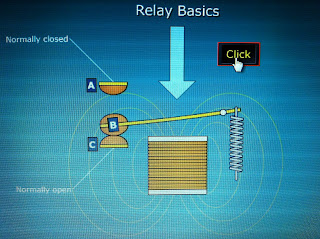
Relay Switch:
What is a car Relay Switch?
- A car relay switch is an electromagnetic switch that uses a low amperage circuit to switch on higher amperage circuit & are very common on cars.
- There are many types of relay switch's but they are all very similar.
- The power usually will come from the battery to control the control coil & the switched circuit.
- Low amps in the control circuit creates magnetism to move the switch points to the other position.
- The switch can now turn on a higher amperage device.
- Some control circuits may have a diode or resistor in parallel to lower the voltage spikes that can hurt electronic control units.

The terms 'normally open' and 'normally closed' refer to a pair of contacts in a relay or switch.
Normally open - means when the switch has made an connection opening up the circuit to allow current flow through the relay switch.
Normally closed means there is no connection and current flow.
Two Reasons to Use a Relay:
A relay will allow you to use a small current to control a larger current. Generally, a relay coil has a relatively high resistance and will require only a small electrical current to engage the contacts.
The second reason to use a relay is to isolate two circuits.
- On the right going down there is some examples of different relays.
This is a simple single pole single throw relay. You can see that there is no normally closed contact. The only time that this relay will pass current through its contacts is when the coil is energized.
This is a single pole double throw relay.

- This pic on the left is showing the normally closed, witch means there is no current flow
- The pic on the right is demonstrating what happens when the becomes normally closed.
- Here we have made our own circuits, Series & Parallel.
- Power source 12V, connecting to positive bar, negative to earth bar, both running to the fuse, then switch, relay switch, light bulb.
- We then tested the voltage drop between each points in the circuit & found that there was one volt drop-age between each point.
- Calibrating the multimeter, so we can get an accurate reading for the voltage drop.
- Having the negative grounded / on earth bar and the positive on positive of the 12V power supply or just by touching the two pins together.
- After calibrating the multimeter we then moved the Positive around the circuit to certain points to find the out whether or not there was any voltage drop.
- There was a voltage drop of 2v between the negative bar and the switch, with the current running through the fuse.
- From the switch to the relay switch there was another drop by 1v.
- Voltage can drop through connections, Conductors, Connectors & through internal resistance.
- The pic below is - Voltage drop test.
- The pic below is - What a relay switch looks like and a small diagram of what you would see when looking at the relay.


No comments:
Post a Comment